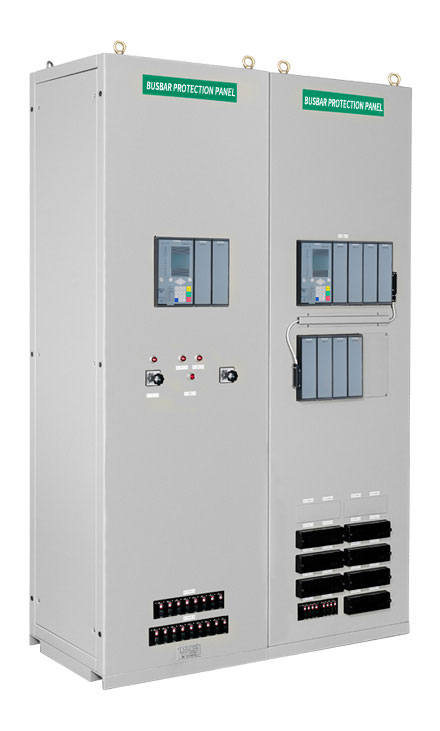
BUSBAR PROTECTION PANEL
Product Overview
In a Power System, substation is an assembly of technology and facility that carry out major functions such as distribution of power, up-down transform voltage and protection and control of system.
Within system, a busbar offers as an important function of which power gets concentrated and distributed through transmission lines. Thus in a busbar, an effect of fault goes on whole substation, which can lead into a severe black out accident by large fault current. In order to prevent this, multiple circuit breaker and switch gear are composed as parts of double busbar protection.
The primary protection method for line protection employs the current differential scheme (87T) as the main protection function, and the FD element applies a low-voltage method using inputs from primary and secondary PTs as an AND condition. The line protection distribution panel utilizes Siemens' advanced technology, employing the centralized type (7SS85) relay to ensure the reliability of protection functions. By integrating accumulated expertise in manufacturing line protection panels, including noise immunity, insulation durability, stable grounding, durability, and layout design, we produce and supply more reliable products.
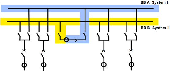
DOUBLE BUSBAR STRUCTURE
With the importance of busbar, in a double busbar structure, protection system is divided into Bus 1 and Bus 2 protection zone. Each of them protects system separately so as to save outage time when there is maintenance and accident. Also through incoming and outgoing current of whole busbar, Check Zone protection function checks internal fault.
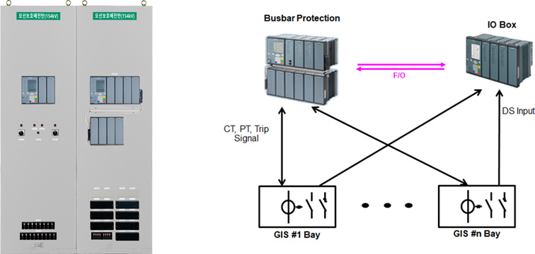
BUSBAR PROTECTION SYSTEM CONFIGURATION
The busbar protection system consists of an IO BOX for inputting the disconnector contact point of each feeder, a current input for each feeder, and a busbar protection relay that receives the voltage input from the busbar and determines the internal failure of the busbar.
FEATURES OF BUS PROTECTION RELAY(7SS85)
-
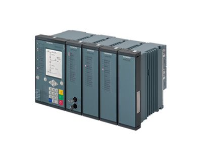
- Digital Protection Relay with 32 Bit high-speed microprocessor
- Substation system configuration in graphics by using DIGSI software
- Supports up to 4 Bus zones, and up to 4 Bus couplers
- Independent and separate setting of Bus Zone and Check Zone
- Accurate detection on internal/external fault by using a differential current protection
- Offers selectable protection zone (Bus zone, Check zone) of multiple busbar system
- Enhancement of stability and speed of a system through fiber-optic connection
- Convenient function such as Remote setting/ Fault analysis by software
DIFFERENTIAL CURRENT PROTECTION CHARACTERISTICS CURVE
-
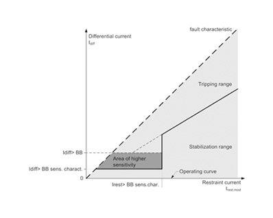
Depending on a ratio between restraint current and differential current, it is divided into trip zone and non-trip zone. A restraint current has a stable restraint property that which compensates a current transformer error and CT saturation.
MAIN FUNCTION
- Current differential protection (independent protection function on each phase)
- User defined logic (CFC-continuous function chart)
- Breaker Failure protection
- Function to prevent mal-function through many fault detection
- Prevention of mal-operation by using CT saturation detection
- Self-diagnosis
- Current transformer ratio mismatches compensation through setting
- Selection possible to one pole/three pole trip function
- Circuit breaker status check function through low current detection
- Metering (current, voltage, active/ reactive power, etc)
- End fault protection between current transformer and circuit breaker
- Event recording function (trip, alarm, fail, etc)
- High speed tripping function
- Using any portable computing device, setting and fault analysis function
(analysis program (DIGSI), Comrade File conversion function) becomes possible
TECHNICAL SPECIFICATION/STANDARD
| Category | Item | Specification | |
|---|---|---|---|
| Rating | Power Supply | Voltage Input | DC : 48~300[V], AC : 80~265[V] (Frequency 50/60[hz]) |
| Power Consumption | Modular Type : Basemodule standard DC 13[W], AC 55[VA]/ Per expansion module : DC 3W, AC 6VA | ||
| Analog | Current(CT) | 1[A] or 5[A], Responsibility : Approx. 0.1[VA] | |
| Power(PT) | 0~200[V], Power Consumption < 0.1[VA] | ||
| Digital Input |
Number of Contacts : Selectable via multiple expansion modules Voltage Range: 24 to 300[VDC] |
||
| Digital Output |
Number of Contacts : Selectable via multiple expansion modules Allowable Current: 5[A](Continuous), 30A for 1s, 250A for 30ms |
||
| Communication | Port | RS-232, RS-485, Ethernet, FO(Fiber Optic) | |
| Protocol | Profibus, DNP3.0, IEC61850, TCP/IP | ||
| Time Synchronization | DCF77/IRIG-B/SNTP/IEEE 1588 | ||