SUBSTATION TOTAL DIAGNOSTIC SYSTEM
System Overview
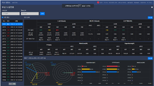
As industries progress, the diversity and advancement of equipment among consumers of power facilities are increasing. Consequently, there is a simultaneous demand for superior quality in power facilities and operational stability. The "Substation Total Diagnostic System" is designed and developed to diagnose and analyze the operational status and signs of faults in real-time for power company substations operating continuously. It provides real-time alerts to operators. The diagnostic information and operational history are optimized for use by power companies as long and short-term operational data, facilitating database management, voltage and equipment condition monitoring, and maintenance planning, all within the realm of leveraging Big Data.
COMPOSITION
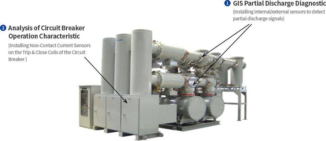
| GIS Element Technology | GIS Partial Discharge Diagnostic | Detecting/Diagnosing Partial Discharge Signals when Electrical Interference and Insulation Issues Occur within GIS to Verify GIS Reliability |
|---|---|---|
| Breaker Operation Characteristic Analysis | Measuring/Analyzing Operating Current and Operating Time during the insertion or opening/closing of a circuit breaker to verify the reliability of the circuit breaker | |
| Transformers Element Technolo | Transformers Partial Discharge Diagnostic | When there's electrical interference or insulation issues within the transformer, detecting/diagnosing partial discharge signals to verify the transformer's reliability |
| Bushing Leakage Current Diagnostic | Measuring/Analyzing Leakage Current Generated by Bushing Insulation Deterioration in Transformers to Verify Bushing Reliability | |
| OLTC(On Load Tap Changer) Diagnostic | Measuring/Analyzing Partial Discharge Signals within OLTC and Motor Drive Current of OLTC to Verify OLTC Reliability | |
| Insulating Gas Diagnostic | Monitoring/Analyzing Insulating Oil Gas Generated from Transformer Insulation Deterioration to Verify Transformer Reliability |
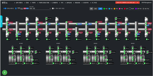
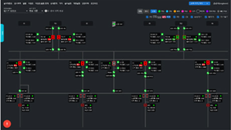
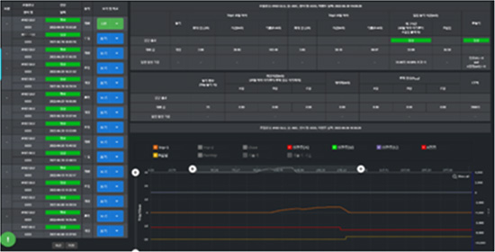
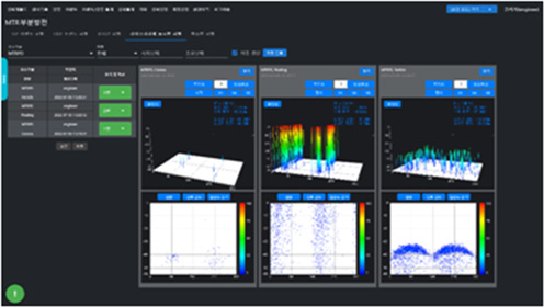
SYSTEM SCREEN CONFIGURATION
Certification
| Electric Strength Test Procedure | IEC 60950-1 : 2005/A2 : 2013 (Edition2.2) | Electrostatic discharge | IEC 61000-4-2 : 2008, Level 3 |
|---|---|---|---|
| High Temperature Operation | IEC 60068-2-2 : 2007 | Radiated Susceptibility | IEC 61000-4-3 : 2008, Level 2 |
| Low Temperature Operation | IEC 60068-2-1 : 2007 | Electric Fast Transient | IEC 61000-4-4 : 2012, Level 3 |
| High Temperature Storage | IEC 60068-2-2 : 2007 | Surge Transient | IEC 61000-4-5 : 2014, Level 3 |
| Low Temperature Storage | IEC 60068-2-1 : 2007 | Conducted Susceptibility | IEC 61000-4-6 : 2013, Level 3 |
| Damp Heat, Cycle test | IEC 60068-2-30 : 2005 | Magnetic Field Immunity | IEC 61000-4-8 : 2009, Level 4 |
| Vibration Response Test | IEC 60068-2-6 : 2007 | Voltage dip/interruption | IEC 61000-4-11 : 2004 |
| Vibration Endurance Test | IEC 60068-2-6 : 2007 |
GIS PREVENTIVE DIAGNOSTIC SYSTEM
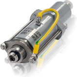
BREAKER OPERATION CHARACTERISTIC ANALYSIS
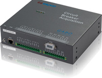
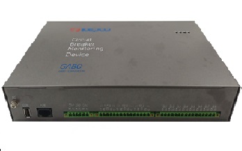
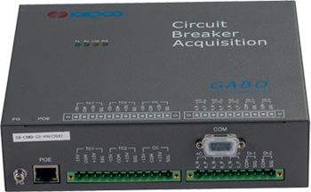
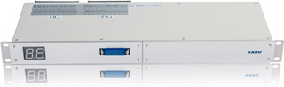
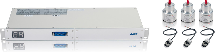
BREAKER OPERATING CHARACTERISTIC ANALYSIS DEVICE
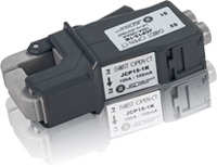
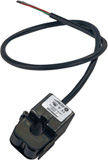
AC CURRENT SENSOR
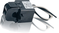
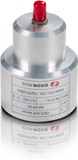
DC CURRENT SENSOR
-
 OR
OR

BREAKER OPERATION CHARACTERISTIC ANALYSIS
The circuit breaker operating characteristic analysis device monitors, analyzes, and diagnoses the mechanical operating characteristics and variations of circuit breakers by utilizing acquired values of Trip/Close coil operating currents, AC load currents, and circuit breaker opening/closing contact signals. This device predicts the timing for preventative maintenance of the circuit breaker based on its types.
Function
| Input Port | Detail |
|---|---|
| Trip Coil : 2 Channel | Detection of coil current during circuit breaker opening |
| Close Coil : 1 Channel | Detection of coil current during circuit breaker closing |
| Current : 3 Channel | Measurement of circuit breaker-specific load currents |
| Auxiliary Contact : 2 Channel | Measuring opening and closing current times using auxiliary contacts |
| Etc |
Accumulation of circuit breaker operation counts analysis of measured data trends |
TRANSFORMER PREVENTIVE DIAGNOSTIC SYSTEM
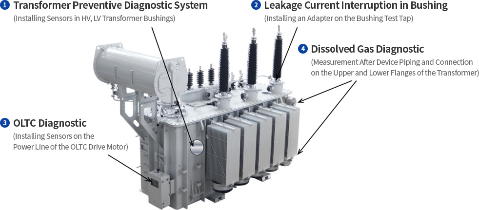
TRANSFORMER PARTIAL DISCHARGE DIAGNOSTIC
Transformer Partial Discharge Diagnostic DAU
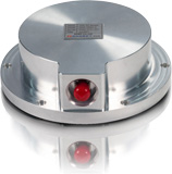
Main Body Partial Discharge Sensor
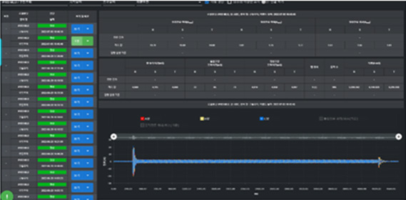
Transformer Partial Discharge Diagnostic
An system that acquires partial discharge signals occurring due to internal anomalies in the M.Tr through sensors, processes the digital signals through the Local Unit's DAU, and transmits them to the diagnostic unit as data CU (communication device). It monitors, analyzes, and diagnoses partial discharge, making assessments based on abnormal indications. This system includes sensors, Local Unit (including DAU and CU), and the diagnostic unit (including diagnostic software).
SYSTEM CONFIGURATION AND SPECIFICATION
| Product | Composition and Specification |
|---|---|
| UHF Senor | 300MHz ∼ 1,800MHz |
| Local Unit |
- DAU (Data Acquisition Unit) - CU (Communication Unit)[IEC 61850 base] |
BUSHING LEAKAGE CURRENT DIAGNOSTIC
Bushing Diagnostic Device
Bushing Diagnostic Adapter

Bushing Leakage Current Diagnostic
The Bushing Leakage Current Analysis Device (BMD) is a diagnostic tool monitoring insulation degradation within the transformer's bushing. It measures and analyzes the capacitance, leakage current, and phase of the transformer's bushing to predict the timing of equipment maintenance.
Function
- Current and Voltage Vector Display
- Compatible with 800 kV, 362 kV, 170 kV Transformer Bushings
- Calibration Function According to On-Site Conditions
- Real-Time Trend Analysis
Measurement and Analysis Items
| Measurement of Transformer Phase Voltage (PT Secondary) | Measurement of Bushing Leakage Current (Phases A, B, C) | Bushing Capacitance Analysis | Bushing Power Factor (%) Analysi | Real-time Trend Analysis |
OLCT DIAGNOSTIC
OLTC Diagnostic Device
OLTC Partial Discharge Sensor
OLTC Current Sensor
OLTC Diagnostic
This is a system that continuously monitors and diagnoses the On-Load Tap Changer (OLTC) of a power transformer. It monitors real-time electrical signals such as arcs and corona discharge occurring due to internal faults in OLTC, and also tracks the filtering pressure, oil temperature, and insulation oil contamination of the Oil Filter Unit (OFU) used for insulating oil filtration. In case of anomalies, it triggers alert functions and provides OLTC monitoring information to the diagnostic unit via the data communication device (CU) of the comprehensive preventive diagnostic system for the substation.
SYSTEM CONFIGURATION AND SPECIFICATION
| Product | Composition and Specification |
|---|---|
| UHF Partial Discharge | UHF Sensor (300MHz~1,200MHz) |
| Drive Unit |
- Drive Motor Operating Current (Excessive and Rated Current, and the Trend of Waveform Pattern Changes) - Motor Drive Contacts (Operating Time, Operating Frequency) |
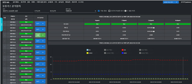
INSULATING GAS DIAGNOSTIC
This device, installed in the incoming power transformer, continuously monitors the state of insulating gas generated due to internal insulation degradation and the increase of moisture that deteriorates insulation. It performs alert functions in case of anomalies and provides insulating gas analysis information to the diagnostic unit through the signal acquisition device (DAU) and data communication device (CU) as per the substation's comprehensive preventive diagnostic system specifications.
| Types of Analytical Gases | Detection Range | Error | |
|---|---|---|---|
| Device Specifications | KEPCO Specifications | ||
| Hydrogen (H2) | 5~5,000 ppm | 5~5,000 ppm | ±10% or ±LDL |
| Carbon Monoxide (CO) | 10~50,000 ppm | 10~5,000 ppm | |
| Acetylene (C2H2) | 3~50,000 ppm | 5~5,000 ppm | |
| Moisture (H2O) | 0~100% RS | 0~100% RS | |
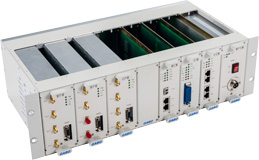
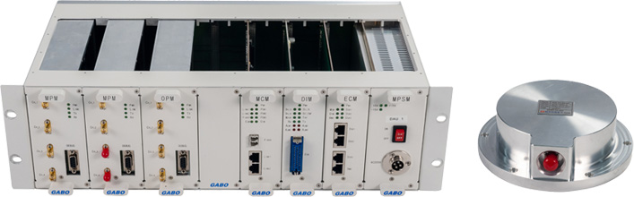
SUBSTATION TOTAL DIAGNOSTIC SYSTEM
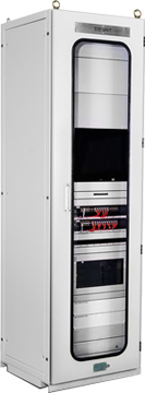
Substation Total Diagnostic UNIT
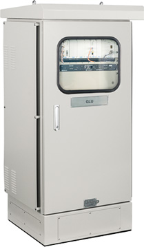
GIS Preventive Diagnostic System GLU
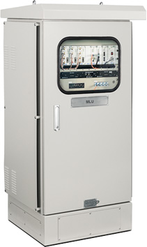
Transformer Preventive Diagnostic System MLU
DIMRUS EQUIPMENT INVENTORY
Dimrus Company was founded in 2009, specializing in the development and manufacturing of cutting-edge diagnostic equipment for stable operation of major high-voltage equipment such as transformers, circuit breakers, and generators.
They provide customers with portable devices for continuous condition monitoring of high-voltage equipment and for precise and versatile diagnostics purposes.
Dimrus products are globally recognized for their performance and quality, selling to more than 45 countries, including major clients in the United States, the United Kingdom, and many others.
Gabo Corporation signed a domestic distribution agreement with Dimrus Company in 2019, aimed at collaborating in the preventive diagnosis field. They exclusively supply Dimrus Company's preventive diagnostic equipment such as the PD-Analyzer (multi-purpose partial discharge diagnostic device), PD-Unit (portable partial discharge diagnostic equipment), Test-PD (portable cable diagnostic equipment) within the domestic market.
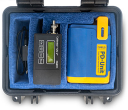
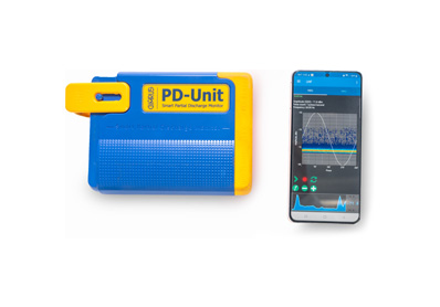
PD-Unit
Portable Insulation State Online Monitoring Device
FUNCTION
Accessory
-
- The basic sensor is built into the main body.
- Additional provided sensors
1) External acoustic sensor
2) HFCT (High-Frequency Current Transformer)
3) TEV (Transient Earth Voltage) sensor
4) UHF frequency sensor
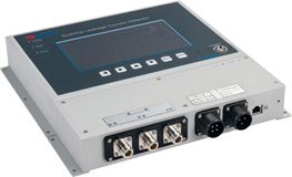
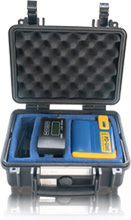
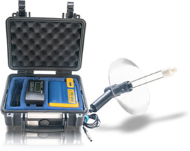
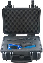
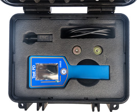
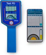
Test-PD
High Voltage Cable Connection and Line Status Online Diagnostic Device
FUNCTION
TECHNICAL FEATURES
1) Acoustic ultrasonic sensor for partial discharge diagnosis
2) Electromagnetic high-frequency PD sensor
3) Capacitive VHF PD sensor
4) Contact-based temperature sensor designed to measure the temperature of connections
5) Power frequency current sensor for measurement synchronization
2. Partial discharge diagnosis occurs across three frequency ranges: ultrasound (AC), high-frequency (HF), and very high frequency (VHF), providing a measurement approach to detect various types of insulation faults.
3. The contact-based temperature sensor evaluates the temperature of connections and is designed to identify points of failure associated with temperature rises.
4. With a current sensor, measurements synchronize with the cable's current, necessary to determine the type of insulation fault in monitored connections.
USE
temperature sensors have holes in the housing cover to enhance sensitivity, while the rest operate through the rear housing cover that can penetrate electronic waves.
2. As you move the Test-PD device along the connector's surface, you can compare areas with increased partial discharge intensity or higher temperatures. This diagnostic method can
estimate the location of insulation faults, and the intensity of each sensor's measured signal is displayed in bar graph format.
3. Depending on the cable discharge form, the device screen displays a red cursor indicating the discharge form in real-time on an approximate cross-section of the cable. In the case of
external noise, the red cursor reacts outside the cable system.
4. The intensity, represented by the number and brightness of the displayed cursors, is designed to vary according to the energy intensity of the actual internal partial discharges in the
equipment.
5. When the device's current sensor detects current in the cable line, the device screen displays the symbol "N," and all diagnoses of faults synchronize with the sine wave phase of the
power. If this signal is absent, the "G" symbol appears on the screen, synchronizing with the internal power source to carry out measurements.
ADVANTAGES
Information from the Test-PD device can be received wirelessly using interfaces such as smartphones or tablets. The image on the left shows the Test-PD device and a smartphone, displaying the same screen as that measured on the device itself.
Secondly, by mounting the Test-PD device on a bar, measurements can be taken in narrow spaces where access to equipment is difficult. The results of these measurements can be viewed on the screen of a smartphone.
DEVICE SPECIFICATION
| CPU frequency range | 2~100MHz, 0.1~2MHz, 40kHz |
|---|---|
| Measurement temperature range, (°C) | -40 ~ +120 |
| Wireless interface | Bluetooth 4.1 |
| Device operating temperatur, ° C | -20 ~ +40 |
| Battery usage tim (Hour) | 10 |
| Device and the main body size (mm) | 205 x 85 x 75, plastic (ABS) |
| Device weight (kg) | 0.3 |
| Transportation case size (mm) | 300 x 270 x 145 |
| Weight of the transport case for the device (kg) | 2.0 |
PD-Analyzer HF / UHF
A wide-area diagnosable partial discharge diagnostic device
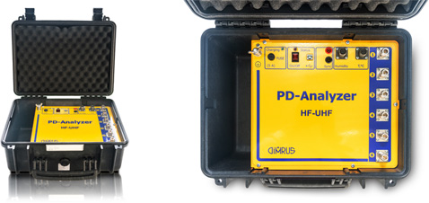
PD-Analyzer HF&UHF
PD-Analyzer HF&UHF Accessory Box
FUNCTION
Parameter
| Number of measurement channels | 6 |
|---|---|
| Operating voltage, kV | > 3 |
| Discharge pulse frequency, MHz | 0.5 ~ 1500,0 |
| Discharge amplitude, pC | 20 ~ 100,000 |
| Computer connection | USB |
| Supply voltage, V, AC / DC | 90 ~ 260 |
| Operating temperature range, °C | 0 ~ 60 |
| Case size, mm | 520 x 435 x 230 |
| Total weight, kg | 25 |
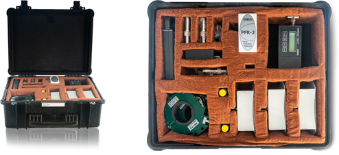
PD Simulator
Partial Discharge Signal Simulator
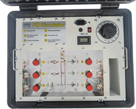
FUNCTION
TECHNICAL FEATURES
2. The simulator for generated fault types has a separate BNC connector for connection with PD measurement devices and oscilloscopes.
3. To simulate various forms of partial discharge, the device has an external voltage adjustment handle, enabling gradual voltage changes to observe the detailed shapes and types of PD occurrences.
Parameter
| Number of measurement channels | 6 |
|---|---|
| Voltage applied to the models of defects, kV | Up to 5.5 |
| PD amplitude in models, V | Up to 2 |
| Simualtor supply voltage | 220V, 1A |
| Diemensions, mm | 475 * 415 * 215 |
| Weight, kg | 20 |