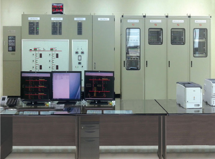
SUBSTATION INTEGRATED CONTROL PANEL
System Overview
This system is a total system for extra high voltage substations such as 154 kv and 345 kV, connecting to electric power facilities in industrial fields.
It provides and analyzes information of electric power facility’s operation, which is needed by an operator. Via control terminal, it also controls electric facility (circuit breaker, switchgear, etc) from remote end.
SYSTEM CONFIGURATION
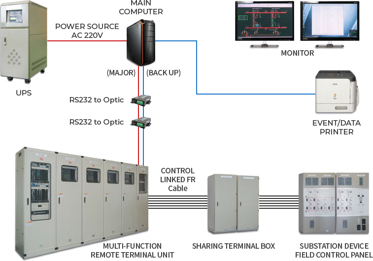
MAIN EQUIPMENTS
-
Main Computer
The most optimal substation integrated control system HMI software embedded into the most updated workstation. It collects and analyzes information real-time basis from remote devices, implementing an accurate control of facilities. Also applied with open architecture system standard, it guarantees extension and flexibility.
-
Event/Data Logger
It is a device that records information about contents of alarms generated from electric power facility and records history of operator’s controlling. Printing is possible by manually or automatically through event printer and data printer.
-
RTU (Remote Terminal Unit)
Obtaining information status of field devices (ON/OFF status of circuit breakers or switchgear) or measurement information (current, voltage, power, etc). RTU sends information to host computers (NEMS, SCADA, substation monitor control devices), analyzes command information sent from host computer in order to control specific devices. Also measuring CT, PT to generate multiple power information (current, voltage, active/reactive power, frequency, power factor, etc)
-
Substation Device Field Control Panel
It forms a power system on a single board in a single line diagram. Through sharing monitor, control, measurement line of field’s devices with RTU, when RTU malfunctions, this panel enables normal operation, control, monitoring.
MAIN CHARACTERISTICS
-
High performance and High Reliability
- Most updated H/W device and S/W
- Redundancy communication function
- Power/communication surge protection function. -
Supports various communication method
- Network communication (TCP/UPD)
- Serial communication -
Remote management
- Remote management functions (monitor/control/measurement) for power facility.
-
Open interface
- International Standard protocol linked function (DNP 3.0)
- Time synchronization priority function
- System security management function -
System diagnosis function
- CPU Board error malfunction diagnosis function
- EISA interface error malfunction diagnosis function
- Event Keyboard error malfunction diagnosis function -
time synchronization function
- Total System time synchronization (Host or HMI based)
- GPS standard time (GPS) signals reception.
MAIN FUNCTION
| Monitor function | - Monitors facility status on Circuit breaker, Switchgear, relay, etc |
|---|---|
| Measurement function | - Offers real-time measurement (BUS, BAY, TR etc voltage, current, active/reactive power) |
| Control function |
- Controls binary condition of circuit breaker, switchgear, switch, transformer Tap Position - Major controls on different phases. |
| Record function | - History of record, alarm generation and management field work for monitor, measurement, control activation |
| Alarm processing function |
- Alarm signal and processing function on real-time basis when there is change in circuit breakers’open and close status, calculating value exceeds critical value, malfunction of device and monitoring element. - Visual, auditory alarm processing on each rating of events. |
| Calculation function | - Through measured values, it can calculate Power Factor, energy absorbed (MWH), deviation on each phase, etc. |
| Pointer management function | - Management functions for monitor/measurement/calculation/device/virtual points. |
| Reporter function |
- Report measuring values by various standards, it sorts values in periods (emergency, daily, monthly, quarterly, yearly, etc). - Automatically creats reports following configured period. |
| Back-up function |
- Automatically backs up event records and each type of reports saved in data base. - Automatic back-up processing that follows configured period. |
| Security function |
- System management for limiting access from unauthorized system user. - System authority management on system unit system. - Various solution of security S/W and H/W that protect system from virus or other malignant program. |
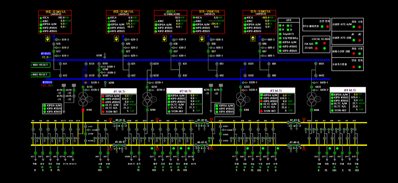
| Graphic functions |
- Displays standard symbol for various electric facilities in substation. - Graphic edit program and viewer for visual information following status of point/difference of measured values. |