EMS RTU(REMOTE TERMINAL UNIT)
System Overview
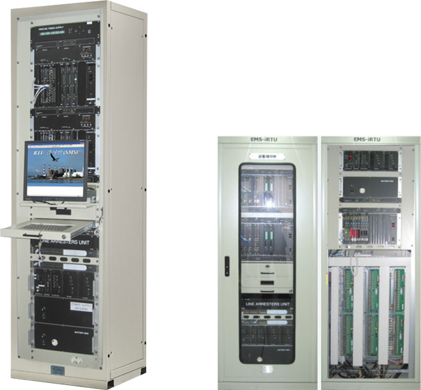
Made for a remote surveillance, measureing and control, EMS-RTU is made for Power system management facility, and it enables an open interface, a high performance, a highly credible distibuted installation, and a remote management.
This device is organized with a main processing device, a field processing device and system management system. And in each control side, it is composed of an operation processing, a communication, input-output control and power.
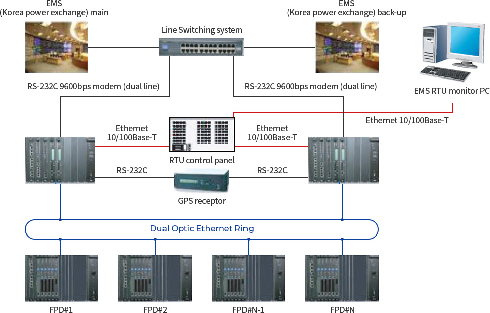
SYSTEM CONFIGURATION
FUNCTION
-
High Performance & High Credibility
- Module protection
- Parallel processing- Redundancy
- Module unit Expansion -
Distributed installation
- Network communication method
- Distributed operation- IED link
-
Remote management
- Remote monitoring terminal equipment connection
- SMS (system management system)- Software DLL (Down Line Load)
- Internet based remote management -
Open Interface
- International standard protocol connection
- Time Synchronization priority- System security management
-
Communication function
- Connection with EMS (energy management system)
- Multi-Protocol and Multi-Tasking
-
System diagnosis function
- System Self-diagnosis and System Simulation Test
- Cold/ Warm Restart, Application
-
Standard Time synchronization function
- System total time synchronization
- GPS standard time reception
MPD (Main Processing Device)
MPD receives commands from EMS and deciphers them in order to implement pertinent replies and processing. Also, it is attached with function that manages system configuration device. Main functions are system self-diagnosis, configuration, database management, communication schedule management, protocol conversion, communication with EMS/ I/O module, HMI connection with System Management System and Time Synchronization management.
Main Processing Unit
-
MPD receives commands from EMS and deciphers them in order to implement pertinent replies and processing. Also, it is attached with function that manages system configuration device. Main functions are system self-diagnosis, configuration, database management, communication schedule management, protocol conversion, communication with EMS/ I/O module, HMI connection with System Management System and Time Synchronization management.
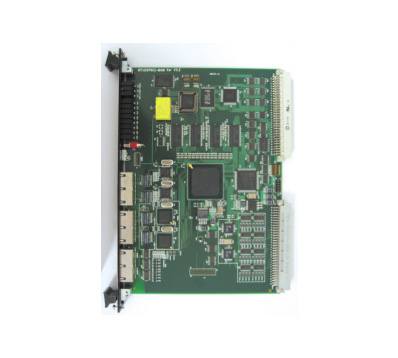
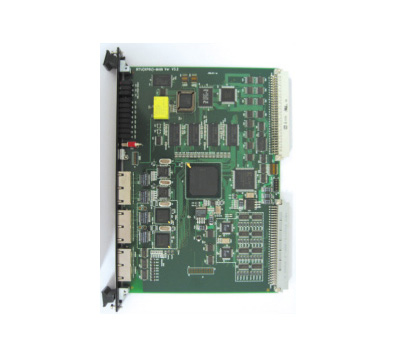
As a SBC (single board computer) for a VMEbus, MPU board is designed adequately to be used as a system control board in a VME bus system.
Using Intel’s [XP 425 Microprocessor), high performance processing is possible. MPU is attached with 256 Mbyte SDRAM, 512 KB EPROM, 16 MB Flash Memory, 8KB NVRAM/RTC, two 10/100 Ethernet Port and two serial ports, for enabling various applications.
| CPU | 32BIT IXP 425 533MHz |
|---|---|
| Memory | SRAM 8MB, SDRAM 256MB, EPROM 512KB, FLASH 16MB, NVRAM 8KB |
| O.S | Real Time Multi Task O.S(VxWorks) |
| Communication PORT | RS-232C 2Port, Ethernet 5Port(100MBpx 2Port, 10MBps 2Port) |
| System Bus Structure | Uses International Standard Bus VME |
| LED Display | PWR, RST, RUN, F/L, VME, SCN, OFA, OFB, LAN1/2/3/4(LINK, ACTIVE), CONSOLE&S1~S4(TX/RX) |
| Features |
- 32Bit CPU with high speed processing capability - CMOS Component with a low power technology - VMEbus Master Interface - High speed DMA supports, for VME32 Standard - Watch-Dog Timer - Battery Back up Function |
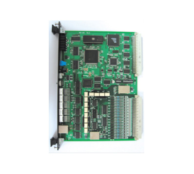
SIO-A : Serial Input Output - Advanced
-
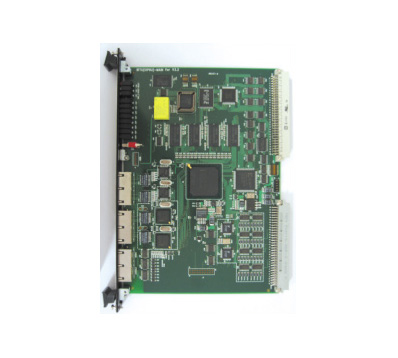
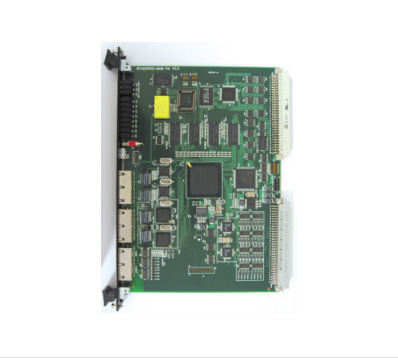
SIO-A board is a VMEbus board developed by using Intel’s [IXP 425 CPU] high-speed 32bit microprocessor.
As a Single Board Computer, it is designed as the most adequate Slave Processing Board in VME bus system. Through high performance 32 Bit data processor, it is a controller board of which offers high credibility. Attached with a protocol conversion function with various high level HOSTs, it is responsible for communication interface. With them, connecting DATA with MPU through sharing memory on VMEbus side. Using four Ethernet ports, simultaneous connection is possible.
| CPU | 32BIT IXP 425 533MHz |
|---|---|
| Memory | SDRAM 64MB, EPROM 512KB, FLASH 16MB, NVRAM 8KB |
| Communication PORT | SDRAM 64MB, EPROM 512KB, FLASH 16MB, NVRAM 8KB |
| System Bus Structure | Uses International Standard Bus VME |
| LED Display | PWR, RST, RUN, VME, 1~8(TX/RX) |
| Features |
- 32Bit CPU with a low power technology. - CMOS Component with a low power technology. - VMEbus Slave Interface - Watch-Dog Timer |
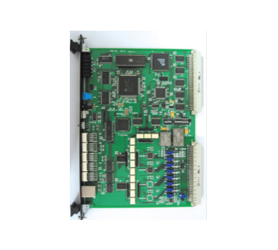
SIO-A : Serial Input Output - Basic
-
SIO-B board is a VMEbus board developed by using Intel’s [IXP 425 CPU] high-speed 32bit microprocessor.
As a Single Board Computer, it is designed as the most adequate Slave Processing Board in VME bus system. Through high performance 32 Bit data processor, it is a controller board of which offers high credibility. Attached with protocol conversion function with various high level HOSTs, it is responsible for communication interface with them, connecting DATA with MPU through sharing memory on VMEbus side.
Using eight serial ports on back side of a board, a simultaneous connection with multiple HOSTs is possible.
| CPU | 32BIT IXP 425 533MHz |
|---|---|
| Memory | SDRAM 64MB, EPROM 512KB, FLASH 16MB, NVRAM 8KB |
| Communication PORT | RS-232C 10Port, Ethernet 2Port(10MBps) |
| System Bus Structure | Uses International Standard Bus VME |
| LED Display | PWR, RST, RUN, VME, 1~8(TX/RX) |
| Features |
- 32 Bit CPU with high speed processing capability - CMOS Component with a low power technology. - VMEbus Slave Interface - Watch-Dog Timer |
FPD (Field Processing Device)
Depending on installation condition, FPD is installed as same place as MPD, or it could be dispersed in power generation or switchyard field. It accommodates interface of surveillance points and control points, and collects and generates digital, analog, and pulse information. Internal communication between MPD and FPD is applied with 100 Mbps optical fiber Ethernet based network communication of redundant ring method. And FPD’s module is composed to meet demands of users. It can accommodate up to sixteen input/output modules.
CPU Module
-
As a major processing module of FPD, a CPU module implements communication with MPD, accommodates I/O function modules responsible of input/output of a field in order to control data input/output of data with a field.
Using Intel’s IXP425 Microprocessor, it could process high performance processing. Attached with 256 Mbyte SDRAM, 512 KB EPROM, 16 MB Flash Memory, 8 KB NVRAM/RTC, two 10/100 Ethernet port, and two Serial Port, it enables various applications.
| CPU | 32BIT IXP 425 533MHz |
|---|---|
| Memory | SRAM 8MB, SDRAM 256MB, EPROM 512KB, FLASH 16MB, NVRAM 8KB |
| O.S | Real Time Multi Task O.S(VxWorks) |
| Communication PORT | RS-232C 2Port, Ethernet 4Port(100MBpx 2Port, 10MBps 2Port) |
| System Bus Structure | Uses International Standard Bus VME |
| LED Display | PWR, RST, RUN, F/L, VME, SCN, OFA, OFB, LAN1/2/3/4(LINK, ACTIVE), CONSOLE&S1~S4(TX/RX) |
| Features |
- 32 Bit CPU with high speed processing capability - CMOS Component with a low power technology. - VMEbus Master Interface - High speed DMA supports, for VME32 Standard - Watch-Dog Timer - Battery Back up 기능 |
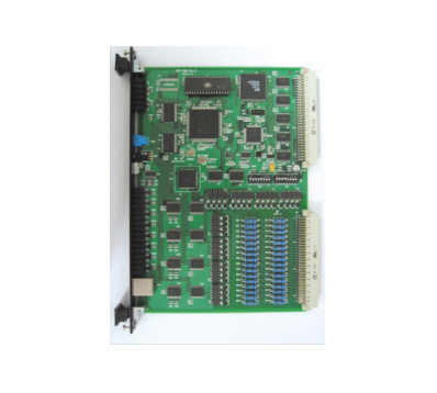
Digital Input Module
-
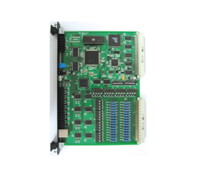
DIM has functions of electric facility breaker open and shut, alarm state, relay auxiliary contact on/off state monitoring, SOE function. It detects electric facility’s block and open and shut state of each relay by using optical isolation method, and transmits this data to common control module.
A state of breaker’s open and shut having a reclosing function, relay’s auxiliary state monitoring such as an alarm state rapidly detects On-Off, Off-On, On-Off-On, Multi-Off state in order to transmit data of which was ordered from SOE function.
| CPU | 32BIT TMS320C32 |
|---|---|
| Memory | SRAM 1MB, EPROM 128KB, 4KB DPRAM, 32KB EEPROM |
| Input Points | 32 Point / Module |
| Input Signal | Dry Contact |
| Monitoring Voltage | 48V DC |
| SOE Resolution | 1msec |
| Debounce Time | 4~64msec (modification available) |
| LED Display | PWR, RST, RUN, VME, S1, S2, Status Display 1~32 |
| Features |
- 32 Bit CPU with high speed processing capability - CMOS Component with a low power technology - VME32 Standard, VMEbus Slave Interface - Watch-Dog Timer - Battery Back up Function |
| Insulation Method | Photo Coupler |
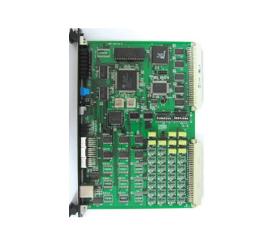
Digital Output Module
-
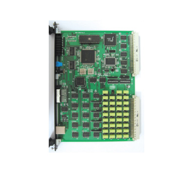
DOM is activated when upper HOST does remote control, and a control output is a pulse signal using Dry-Contact point. It is used when a Trip/Close of same voltage performed and it is not activated when more than two breakers are chosen simultaneously.
| CPU | 32BIT TMS320C32 |
|---|---|
| Memory | SRAM 1MB, EPROM 128KB, 4KB DPRAM, 32KB EEPROM |
| Output Points | 16 Point / Module |
| Output Signal | Relay Contact |
| Holding Time | 100ms ~ 6000ms(Adjustable) |
| Controlling Voltage | 24V DC |
| LED Display | PWR, RST, RUN, VME, S1, S2, OPR, RLY, Output 1~32 |
| Features |
- 32 Bit CPU with high speed processing capability - CMOS Component with a low power technology. - VME32 Standard, VMEbus Slave Interface - Watch-Dog Timer - Check Before Operate function |
| Insulation Method |
Relay and Secondary division by Relay Output side is insulated electronically (Photo Coupler insulation) |
Analog Input Module
-
AIM converts analog signal attained from electricity facility to digital signal which is sent to MPD. And its input is supplied at conversion device.
| CPU | 32BIT TMS320C32 |
|---|---|
| Memory | SRAM 1MB, EPROM 128KB, 4KB DPRAM, 32KB EEPROM |
| Input Points | 16 Point / Module |
| Input Signal | Can be selected between 0~1mA, 4~20mA, 0~5V |
| Output Signal | 16 BIT Digital |
| LED Display | PWR, RST, RUN, VME, S1, S2 |
| Features |
- 32 Bit CPU with high speed processing capability - CMOS Component with a low power technology. - VME32 Standard, VMEbus Slave Interface - Watch-Dog Timer |
Analog Output Module
-
AOM is used for generator’s output control. A control output is an analog value (Set Point), and it is combined with a control facility (DCS). A control output maintains its current value until next command. A set of point output module displays information received from center device into decimal number, and sends output of control and alarm signals.
| CPU | 32BIT TMS320C32 |
|---|---|
| Memory | SRAM 1MB, EPROM 128KB, 4KB DPRAM, 32KB EEPROM |
| Output Points | 4 Point / Module |
| Output Signal | Can be selected between 4~20mA, 0~5V |
| Designated Output | 16 BIT Digital |
| LED Display | PWR, RST, RUN, VME, S1, S2 |
| Features |
- 32 Bit CPU with high speed processing capability - CMOS Component with a low power technology - VME32 Standard, VMEbus Slave Interface - Watch-Dog Timer |
| Insulation | Photo Coupler |
Pulse Input Module
-
PIM is used for pulse data processing. Pulse data is generated at electricity facility (e.g.: generation capacity). Similar to digital data, it uses and processes an Optical Isolation method. Data changed in its state is saved and integrated within current. Followed from EMS command signal, it transmits and processes data.
| CPU | 32BIT TMS320C32 |
|---|---|
| Memory | SRAM 1MB, EPROM 128KB, 4KB DPRAM, 32KB EEPROM |
| Input Points | 8 Point / Module |
| Input Current | Less than 6mA |
| Input Voltage | DC 48V (Pulse Count) |
| Debounce Time | 4 ~ 64ms |
| LED Display | PWR, RST, RUN, VME, S1, S2 |
| Features |
- 32 Bit CPU with high speed processing capability - CMOS Component with a low power technology. - VME32 Standard, VMEbus Slave Interface - Watch-Dog Timer |
| Insulation | Photo Coupler |
Pulse Output Module
-
POM is used when a generator automatically sends calculated fluctuation value at EMS.
And it is sent as pulse-width signal using a contact point without an application of check before operation function.
| CPU | 32BIT TMS320C32 |
|---|---|
| Memory | SRAM 1MB, EPROM 128KB, 4KB DPRAM, 32KB EEPROM |
| Input Points | 4 Point / Module |
| Output Relay Burden | DC 125V, 0.5A (Dry Contact) |
| Activation Method | Direct Operate |
| Relay Activation Time Control Range | 200ms ~ 1.4sec (variable 200ms STEP) |
| LED Display | PWR, RST, RUN, VME, S1, S2 |
| Features |
- 32 Bit CPU with high speed processing capability - CMOS Component with a low power technology - VME32 Standard, VMEbus Slave Interface - Watch-Dog Timer |