SUBSTATION AUTOMATION OPERATING SYSTEM(SA)
System Overview
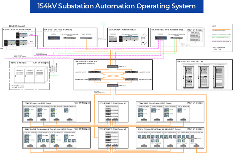
The system is comprised of Substation-Automation Operation Processing Device which plays the roles of calculating various operation information on the field instruments transmitted from IEC61850-based IED and RTU devices, performing database-related processing, showing analysis/diagnosis information on the acquired data, executing processing of operator’s commands, and informing the operator by audible and visible methods for all power equipment of a substation. Substation Automation System for application to IEC61850-based digital substations by configuring the devices such as Substation-Automation Information Connecting Device equipped with functions capable of connecting information on monitoring/control/measurement/protection for power equipment with SCADA Host system through connection of IEC61850-based IED and RTU.
CONFIGURATION DIAGRAM
SYSTEM COMPONENTS
-
Substation-Automation Operation Processing Device
It can identify contents of monitoring and controls points and can operate facility in a conversation form with the computer through a display device without sophisticated knowledge on computers, where the Display device is realized to allow easy determination of equipment system status at a glance by having batch display of required data(measuring instrument, state. alarm, etc.) together with graphic in the same screen.
By installation of (external) programs such as IED fault analysis program or IED setting program in the SA operating system, it can be used independently of the programs dedicated to the SA operating system. -
Printer for outputting of operation data
It is connected to the SA operation device through USB or Ethernet interface, and can output information such as operation data.
-
Uninterruptible power supply
It is operated for SA operation processing device by being connected as a substation battery system with a vertical stand-alone type of structure and can supply power supply to SA operation processing device upon substation power outage.
-
Substation-Automation Information Connecting Device
It receives information from power equipment from multitude of IED’s and RTU’s, provides the relevant information to Regional Control Center(Sub-Control Center) and Distribution Automation System, control commands from which are transmitted to IED or RTU to allow control of substation power facility from SCADA host (RCC/SCC/DAS).
Substation-Automation Information Connecting Device is designed and realized so as to conform to the communication protocol defined in IEC61850 to transmit/receive information to/from IED. -
Time synchronization device
It receives GPS time information through a GPS receiver, and provides GPS time information through SNTP(Simple Network Time Protocol).
-
Power supply device
It is a structure in front of SA system panel. which facilitates attachment/detachment for convenience of inside checkup and maintenance/repair of each component instrument, allowing operation and manipulation supplying power.
-
Ethernet switch
It is composed of access ethernet switch connected to SA operation device, IED, etc. and backbone ethernet switch to which the access switches are connected.
-
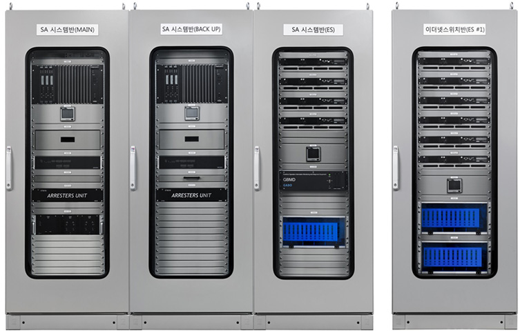
Panel configuration
It is the distribution panel supplied for application to substation’s SA system, and composed of SA system panel (Main) including Information Connecting Device, SA system panel (Back up), SA system panel including ethernet switch (ES), and ethernet switch panel.
MAJOR FUNCTIONS
Operation program for operation device/Substation-Automation Information Connecting Device.
【Operation (Execution) program for Substation-Automation Operation Processing Device/Substation-Automation Information Connecting Device】
It can conveniently perform power monitoring engineering including overall power system diagram, partial power system diagram, setup program for operation environment, various editor programs including graphic editor, various report programs including daily forms, communication programs for communication other than IED, etc.
-
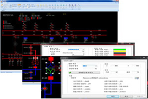
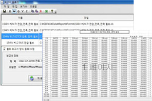
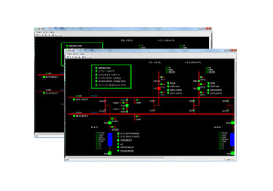 Overall power system diagram
Operation screen of monitoring, measurement, control for overall power equipment of substation.
Monitoring of partial power system diagramIt can configure separate partial operation screen, and represent field operation situations per information group by configuring detailed power system monitoring operation per feeder, state and control screens per gas and equipment group.
-
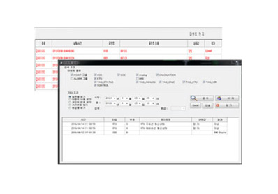 Event output
Immediately upon occurrence of alarm(state, analog), the operator is enabled to check in real time by outputting event in the event bar and alarm sound for the relevant event, and alarm history can be inquired later by being saved in DB.
The contents of event occurrence are outputted per event class in the event bar.▶ Event output in Event Bar ▶ Event search
Editing program
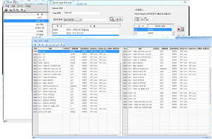
Graphic editor
Graphic editor is provided to display diversified system forms and states in single-line system diagram using graphic object for outputting or saving of the screen.
Example for overall system diagram / Menu bar for graphic editor / Image setup in graphic editor / Symbol setup in graphic editor
Point editor
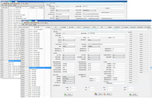
Monitoring point editor
/ Measurement pointer editor
Virtual point editor
/ Calculation point editor
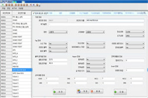
Device point editor
Report editor
It is the software which allows generation, addition, revision, deletion of all documents for reporting, and can record information related to point in the report by connecting the report form and the database point.
It prepares breaking news, daily, monthly, quarterly, yearly, etc. by using convenient Excel form, and can reflect additional calculation results in the report by using calculation operator.
Report register / Report form
Trend editor
It is the editor taking charge of a series of editing to display trend for the relevant measurement values in the screen (LCD) or save in an auxiliary memory device by grouping measurement data, and includes functions for assigning measurement points to each trend viewer or enabling generation, addition, revision, and deletion of trend viewer itself.
It outputs information measured in real time based on the set-up trend information and the trends of measured values in the screen through history information saved in DB.
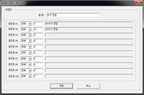
Trend registration
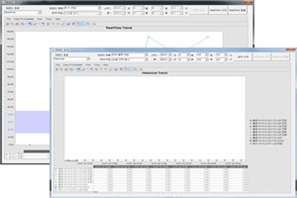
Output of trend for real-time measurement / Out of historical trend
Authority editor
User ID’s and passwords per security class are managed to maintain security of system operation data and prevent mal-operation of equipment. System administrator (Super User) can add user ID’s and set up authority for each account per function.
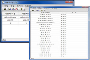
User management / Authority editing
Tabular editor
Information on the points not dealt with in the single-line system diagram is provided through Tabular Page, etc.
Tabular editing registration / Tabular output
Communication program
-
 Communication program for information linkage device
Communication linkage with all devices is independently performed for communication software linked with multitudes of IED and RTU, without affecting communication disability with a particular device or linkage with devices of different performance.
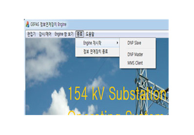
Substation-Automation Operation Processing Device consists of DNP Master process for linkage with RTU, and MMS Client program for linkage with IED’s, while the Substation-Automation Information Connecting Device additionally requiring linkage with the upper-level SCADA Host is independently performed by DNP Slave program, and is designed not to affect other devices.
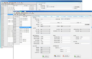
IEC61850 client
Contents defined in IEC61850 standard shall be complied with, and the communication program with conformance to IEC61850 Client certified is loaded.
SCL files received from IED equipment through SCL Manager program are imported for DB conversion of IED configuration information and point information.
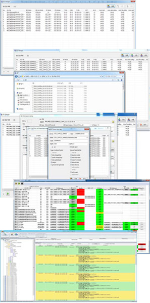
IED configuration management (SCL Manager) / IED information Import / Setting for use status of IED DB / Setting for IED REPORT CONTROL / Checking for real-time data of power equipment / IEC61850 communication log
DNP Master communication program
Main and preliminary connections can be made with equipment other than RTU and IED equipped with DNP slave communication specification by DNP serial or DNP TCP communication. It is equipped with manual switching function through communication environment setup, DNP Master program and communication log function, etc.
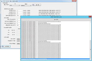
Setting for DNP Master communication environment / DNP Master communication log
DNP Slave communication program
Substation-Automation Information Connecting Device is equipped with DNP slave communication specification for communication with the upper-level SCADA Host(SCC/RCC/DAS/NCC).
Main and preliminary communications are possible by DNP serial or DNP TCP communication. it is equipped with functions of communication environment setup, Host-related communication setup, and communication log etc.
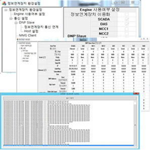
DNP Slave setup for information linkage device / HOST-related communication setup for Information Connecting Device / Host communication log for Information Connecting Device